
A screw feeder may look relatively simple from the outside, but in a modern pulp mill its job can be far more demanding than merely conveying raw material from one piece of equipment to another.
When fibrous material has to enter a pressurized steaming, impregnation or refining system, the feeder must handle several tasks at the same time. It needs to transport the material continuously, compress it, remove part of the free water, create a dense material plug and prevent high-pressure steam from flowing backward through the feeding line.
This is where a plug screw feeder, sometimes called a compression screw feeder, becomes particularly important.
Unlike a conventional screw conveyor, which mainly moves material horizontally or at an incline, a plug screw feeder is designed to deliberately compress the material as it travels through the machine.
The compressed material forms a dense plug that acts as a pressure seal between atmospheric-pressure equipment and the downstream high-pressure process.
For pulp and paper production, this design can improve process stability, reduce steam losses and prepare wood chips or other fibrous raw materials for more effective steaming or chemical penetration.

What Is a Screw Feeder in a Pulp Mill?
A pulp mill screw feeder is a heavy-duty feeding device used to continuously introduce fibrous raw materials into the next stage of the production process.
Depending on the process configuration, it may be installed before:
- steaming equipment;
- impregnation systems;
- pressurized treatment equipment;
- refiners;
- digesting or pretreatment systems;
- chemical treatment equipment.
The screw rotates inside a robust housing and pushes the incoming material toward the discharge end.
However, the screw geometry and internal structure are designed so that the available space for the material gradually decreases.
As the material moves forward, it is progressively compressed.
In an appropriately designed plug screw feeder, this compression produces several effects:
- excess water can be squeezed out;
- large or loosely packed pieces can be compacted and partially broken apart;
- the bulk density of the material increases;
- a dense material plug is formed;
- the plug helps isolate the upstream feeding section from downstream steam pressure.
This is the fundamental difference between a pulp mill plug screw feeder and an ordinary screw conveyor.
How Does a Plug Screw Feeder Work?
The operation can be understood as several continuous stages.
1. Material Feeding
Raw material enters the screw feeder through the inlet.
Depending on the pulp production process, the feed material may include wood chips or other prepared fibrous biomass.
At this stage, the material is usually relatively loose and contains voids between individual particles.
A correctly designed inlet is important because irregular fibrous materials do not always flow as easily as granular materials.
Poor hopper design may lead to:
- bridging;
- uneven feeding;
- surging;
- incomplete screw filling.
Stable material supply therefore has a direct influence on feeder performance.
2. Progressive Compression
As the screw rotates, the material is transported forward.
The internal screw arrangement creates progressively increasing compression.
Instead of allowing material to remain loose throughout the entire screw, the feeder reduces the available volume as the raw material travels toward the discharge side.
This can be achieved through the relationship between:
- screw pitch;
- screw diameter;
- shaft geometry;
- internal restriction;
- back pressure.
The material becomes increasingly compact.
For fibrous raw materials, controlled compression is especially useful because the raw material contains a considerable amount of compressible void space.
3. Compression, Tearing and Dewatering
According to the operating principle of this type of screw feeder, the material is subjected not only to axial movement but also to mechanical squeezing and shearing.
During this process, the raw material may be:
compressed, mechanically opened or torn, and partially dewatered.
This preparation can be beneficial before the material enters downstream treatment.
Removing excess free water and opening the structure of the material can help create more suitable conditions for subsequent steam treatment or chemical impregnation.
The purpose is not simply to make the material smaller.
More importantly, mechanical treatment can change the physical condition of the material before the next processing stage.
4. Formation of a Dense Material Plug
One of the most important functions of a plug screw feeder is the creation of a material plug.
As compression increases, the loose feed material becomes a dense compacted mass near the discharge section.
This plug itself becomes part of the pressure-sealing system.
The concept is particularly useful because pulp mill production lines may have very different pressures on opposite sides of the feeder.
The upstream feeding system may operate near atmospheric pressure, while downstream equipment can contain:
- high-temperature steam;
- saturated steam;
- elevated pressure;
- treatment chemicals.
Without an effective pressure barrier, steam could flow backward toward the feeding system.
The compacted material plug helps prevent this blowback.
Why Is Back-Pressure Control Important?
The screw feeder shown in the supplied equipment information is designed to operate together with a T-shaped pipe equipped with a back-pressure device.
This is an important part of the system.
Compression cannot be generated efficiently if the material has no resistance at the discharge end.
The back-pressure arrangement provides controlled resistance against the outgoing material.
This resistance allows the screw to compress the raw material before discharge.
The result is a more stable material plug.
A properly controlled back-pressure system can help achieve:
- stable compression;
- improved plug density;
- reliable pressure sealing;
- reduced steam blowback;
- more uniform feeding.
At the same time, back pressure cannot simply be increased without limit.
If the resistance becomes excessive, operating torque can rise rapidly and increase the risk of:
- motor overload;
- screw wear;
- blockage;
- mechanical damage.
For this reason, screw feeder design requires a balance between plug sealing performance and mechanical loading.
Pressure Sealing Against High-Temperature Steam
Once the dense plug has formed, it creates a physical barrier inside the feeding system.
This barrier helps isolate the upstream equipment from downstream high-pressure steam.
In pulp processing systems involving steaming or pressurized pretreatment, this is one of the most important functions of the feeder.
Instead of relying only on a mechanical valve to isolate the two pressure zones, the system takes advantage of the compressed raw material itself.
A stable plug can help reduce:
- steam escaping backward;
- pressure fluctuation;
- disturbances to upstream material flow;
- energy losses.
This is why plug screw feeders are often considered process equipment rather than simple material-handling machines.
Expansion After Discharge
An interesting part of the process happens immediately after the material exits the high-compression area.
Inside the screw feeder, the material has been tightly compressed.
After leaving the discharge restriction, the external mechanical pressure suddenly decreases.
The compacted material can then expand.
This expansion opens the material structure again.
The combination of:
compression → discharge → rapid expansion
can improve the accessibility of the fibrous raw material.
If the downstream process contains steam or chemical solution, the opened structure allows these treatment media to penetrate the material more effectively.
Improved Steam and Chemical Impregnation
This is particularly valuable in pulp production.
Steam and chemicals must penetrate the raw material as uniformly as possible.
If the material remains dense internally or poorly opened, penetration may be uneven.
Some areas can be overtreated while others are undertreated.
Mechanical compression followed by expansion can provide improved conditions for subsequent impregnation.
Depending on the production process, the material after leaving the feeder may be exposed to:
- saturated steam;
- process steam;
- chemical liquor;
- other process chemicals.
This combination of mechanical preparation and downstream treatment can contribute to more uniform processing.
Plug Screw Feeder vs Screw Conveyor
Although the two machines may appear similar, their purpose is different.
| Feature | Plug Screw Feeder | Screw Conveyor |
| Main purpose | Metering, compression and feeding | Material transportation |
| Material compression | High | Usually low |
| Plug formation | Yes | Normally no |
| Pressure sealing | Yes | Normally no |
| Dewatering | Possible | Usually not |
| Back-pressure system | Common | Usually unnecessary |
| Steam isolation | Important function | Not typical |
| Typical pulp mill role | Feeding pressurized processes | Moving bulk material |
A screw conveyor mainly answers the question:
How can we transport this material?
A plug screw feeder answers a more demanding question:
How can we continuously feed this material into a pressurized process while compressing it and preventing steam from escaping backward?
That distinction should be considered when selecting equipment.
Major Components of an Industrial Screw Feeder
Although designs vary between manufacturers and applications, a typical heavy-duty pulp mill screw feeder may include several key sections.
Feeding Section
The feeding section accepts material from upstream equipment and provides a continuous supply to the screw.
Good inlet design is particularly important when handling irregular wood chips or fibrous materials.
Screw Assembly
The screw is the main working component.
Its geometry directly affects:
- feeding capacity;
- compression ratio;
- power demand;
- residence time;
- plug formation.
The screw must withstand high torque and continuous abrasive mechanical loading.
Compression Section
The compression zone gradually increases material density.
The design must generate sufficient compression without creating unacceptable mechanical loads.
This is where screw geometry becomes significantly more important than in ordinary conveying equipment.
Housing
The housing contains and supports the screw while resisting internal mechanical forces.
For demanding industrial applications, housing rigidity is important because the feeder operates under high compression loads.
Drive System
The drive system normally includes:
- electric motor;
- gearbox;
- coupling;
- supporting drive components.
Large plug screw feeders can require substantial installed motor power because compression consumes considerably more energy than ordinary conveying.
Back-Pressure Device
A back-pressure mechanism controls resistance at the discharge end and helps establish a stable plug.
Correct adjustment is essential for both sealing performance and equipment load.
T-Pipe Arrangement
In some pulp mill configurations, the feeder is connected to a T-shaped discharge pipe.
This arrangement can integrate the screw feeder with the downstream steam or treatment system while supporting plug formation and controlled discharge.
Typical Screw Feeder Capacity and Motor Power
Based on the equipment information supplied for this article, the screw feeder series includes the following models:
| Model | Processing Capacity | Motor Power |
| WLQ13.5 | 150–250 t/d | 132–200 kW |
| WLQ17 | 300–600 t/d | 355–560 kW |
| WLQ20 | 500–1000 t/d | 450–800 kW |
| WLQ24 | 800–1500 t/d | 710–1000 kW |
These figures illustrate an important point about industrial plug screw feeders.
The machine may consume considerably more power than a conventional screw conveyor of similar apparent size because a large part of the drive energy is used for material compression rather than transportation alone.
Actual equipment selection should not be based only on daily tonnage.
The properties of the raw material and the downstream pressure conditions must also be considered.
How to Select the Right Screw Feeder
Choosing a plug screw feeder begins with understanding the material.
Two plants processing the same nominal capacity may require different feeder configurations because their raw materials behave differently under compression.
Several parameters should therefore be evaluated.
1. Required Production Capacity
The first parameter is usually production capacity, commonly expressed in:
tons per day (t/d)
or sometimes:
tons per hour (t/h).
However, rated capacity alone is not enough.
The equipment must also handle variations in instantaneous flow.
2. Raw Material Type
The physical behavior of wood chips can differ substantially from other fibrous materials.
Important characteristics include:
- particle shape;
- chip dimensions;
- fibre length;
- bulk density;
- compressibility.
These properties influence screw loading and plug formation.
3. Moisture Content
Moisture has a major effect on compression behavior.
Higher moisture content may change:
- friction;
- dewatering performance;
- plug density;
- torque;
- material flow.
For reliable equipment sizing, moisture conditions should therefore be specified as accurately as possible.
4. Particle Size Distribution
A screw feeder does not handle perfectly uniform particles.
Industrial raw materials usually contain a size distribution.
Oversized pieces may cause:
- unstable feeding;
- local overload;
- blockage;
- higher wear.
Very fine material can also behave differently from larger particles when compressed.
5. Bulk Density
Bulk density affects the relationship between volumetric throughput and mass throughput.
For example, two feeders handling the same physical volume may have very different tonnage capacities if one material has twice the bulk density of the other.
6. Compression Requirement
Different processes require different plug densities.
A feeder designed primarily for controlled feeding may require less compression than equipment that must create a pressure-tight plug.
This has a major influence on:
- screw design;
- motor power;
- gearbox torque;
- back pressure.
7. Downstream Pressure
The pressure difference across the feeder must be considered.
Higher downstream operating pressure generally places greater demands on plug stability.
The complete system should therefore be designed according to actual process conditions rather than selecting the feeder independently.
Why Motor Power Can Be High
One question customers frequently ask is why a pulp mill screw feeder requires such a large motor.
The answer is compression.
An ordinary conveyor uses most of its energy to overcome friction and move material.
A plug screw feeder must additionally generate enough force to compress large quantities of fibrous material into a dense plug.
The required torque can increase further when:
- moisture changes;
- feed becomes denser;
- particle size increases;
- back pressure increases;
- material flow becomes unstable.
For this reason, selecting a drive only according to average power consumption can be risky.
The drive system should also provide sufficient torque margin for changing operating conditions.
Common Screw Feeder Problems
Even a properly designed feeder can experience operating problems if upstream or downstream conditions vary significantly.
Several issues deserve special attention.
Material Blockage
Blockage may be caused by:
- oversized particles;
- foreign objects;
- excessive back pressure;
- irregular feeding;
- unsuitable moisture levels.
The solution should focus on identifying the cause rather than simply increasing motor power.
Excessive Motor Load
High current or torque can indicate:
- excessive material compression;
- abnormal back pressure;
- mechanical wear;
- foreign material;
- excessive feed rate.
Long-term overloaded operation can reduce the life of the motor, gearbox and screw assembly.
Unstable Plug Formation
If plug density is unstable, the pressure seal may also fluctuate.
Possible causes include variations in:
- material moisture;
- feed rate;
- bulk density;
- particle size;
- back-pressure setting.
Stable upstream feeding is therefore essential.
Steam Blowback
Steam escaping toward the feeding side is a serious operating issue.
Possible causes can include:
- insufficient plug density;
- low material feed rate;
- incorrect back pressure;
- worn screw components;
- unsuitable process settings.
The entire feeding and pressure-sealing system should be evaluated together.
Screw Feeder Maintenance
Preventive maintenance is important because these machines operate continuously under substantial mechanical load.
Routine inspection should focus on several areas.
Screw Wear
The screw experiences continuous contact with compressed material.
Excessive wear can gradually reduce compression capability.
Housing Wear
The internal housing should be inspected for abrasion and abnormal clearances.
Growing clearance between the screw and housing can affect feeding performance.
Gearbox and Bearings
Drive components should be checked according to the manufacturer's recommended lubrication and inspection intervals.
Unusual temperature, vibration or noise should be investigated promptly.
Back-Pressure Mechanism
The back-pressure device should move correctly and maintain stable resistance.
Mechanical sticking can cause severe fluctuations in screw load.
Motor Current
Motor current is useful for observing long-term operating trends.
A gradual increase in power demand may indicate changes in:
- material condition;
- mechanical clearance;
- back pressure;
- equipment wear.
Operational data can therefore help identify developing problems before an unexpected shutdown occurs.
Applications of Screw Feeders in the Pulp and Paper Industry
Plug screw feeders can be used in several parts of pulp production where controlled material feeding and pressure isolation are required.
Common applications include:
Wood Chip Processing
Wood chips may be compressed before entering steaming or chemical treatment systems.
Mechanical and Chemi-Mechanical Pulping
Processes involving heat, pressure and chemicals require reliable transfer of raw material between different process zones.
Steam Pretreatment
A dense material plug can separate atmospheric-pressure feeding equipment from pressurized steaming equipment.
Chemical Impregnation
Mechanical compression followed by expansion can create favorable conditions for process chemicals to penetrate fibrous material.
Biomass and Fibrous Material Processing
The same general feeding principle can also be applied to selected biomass processes where compressible fibrous raw materials must enter a pressure vessel or treatment system.
The specific feeder design, however, should always be matched to the material.
What Information Should Be Provided When Requesting a Screw Feeder?
For a manufacturer to recommend a suitable model, providing only "500 tons per day" is usually not enough.
A useful technical inquiry should include:
- raw material;
- required production capacity;
- moisture content;
- bulk density;
- typical particle size;
- maximum particle size;
- upstream equipment;
- downstream equipment;
- operating pressure;
- operating temperature;
- chemical conditions;
- required material of construction;
- available motor voltage and frequency.
Providing these parameters early can make equipment selection much more accurate.
Frequently Asked Questions
What is the difference between a screw feeder and a screw conveyor?
A screw conveyor primarily transports bulk material. A plug screw feeder controls feeding while also compressing the material and, in many pulp mill applications, creating a dense plug for pressure sealing.
Why does a pulp mill screw feeder compress the material?
Compression helps increase material density, remove part of the free water and create a plug capable of reducing steam blowback from downstream pressurized equipment.
What is a plug screw feeder?
A plug screw feeder is a screw feeding machine designed to compress material into a dense plug before discharge. The plug can function as a pressure barrier between atmospheric and pressurized process zones.
Can a screw feeder handle wood chips?
Yes. Heavy-duty screw feeders are commonly designed for fibrous raw materials such as prepared wood chips. The specific screw geometry and drive power should be selected according to chip size, moisture, density and required capacity.
Why is a back-pressure device used?
The back-pressure device creates controlled resistance at the discharge end, allowing the screw to compress material and maintain a stable plug.
How do I select screw feeder capacity?
Capacity should be selected based on more than daily production tonnage. Raw-material moisture, particle size, bulk density, compression requirement and downstream pressure should all be considered.
Conclusion
In pulp production, a screw feeder can be far more than a simple conveying device.
A properly designed plug screw feeder combines several functions within one continuous process:
feeding, compression, mechanical opening, partial dewatering, plug formation and pressure isolation.
When the compressed material leaves the feeder and expands, it can also become more receptive to downstream steam or chemical treatment.
For mills using high-temperature and pressurized processing systems, the performance of the screw feeder can directly influence:
- feeding stability;
- steam sealing;
- energy efficiency;
- downstream impregnation;
- production continuity.
For this reason, selecting a screw feeder should not be based only on nominal throughput.
Material properties, operating pressure, moisture, particle size, compression requirements and downstream process conditions must be evaluated together.
A properly matched screw feeder provides not only reliable material handling, but also a stable connection between atmospheric feeding equipment and the pressurized heart of the pulp production process.
Case
-
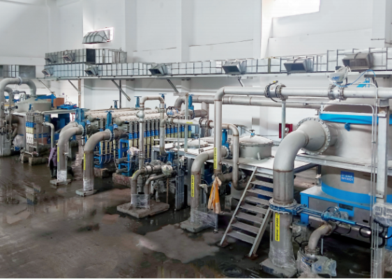 Yunda’s Complete Stock Preparation System for Jinlong’s 6600 mm Packaging Paper Project Enters Commissioning Stage
-
 Yunda Secures Orders for Premium Tissue Paper Projects at Two Yusen Group Production Bases
-
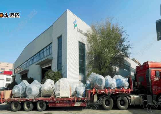 Yunda Successfully Ships the Complete Stock Preparation System for Hengan Group’s Tissue Paper Project
-
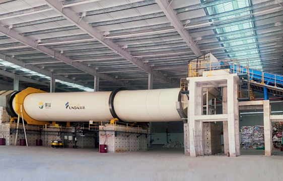 Yunda’s Complete Stock Preparation Systems for Guangxi Xiongfu Paper’s 300,000 t/a Grayboard Paper Project Successfully Start Up
-
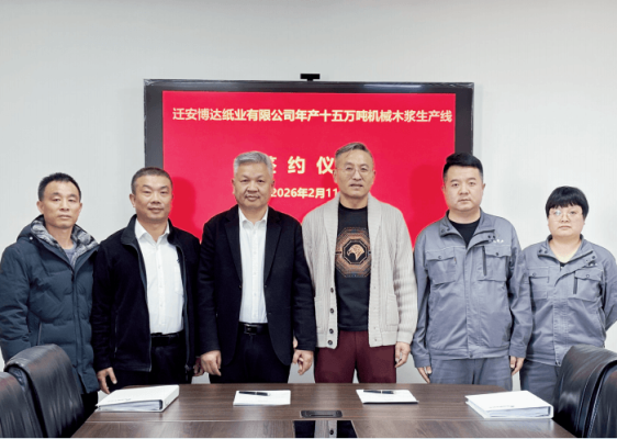 Yunda Wins the Full-Line Pulping Equipment Order for Qian’an Boda’s 150,000-Ton Bleached Chemi-Thermomechanical Pulp (BCTMP) Project
-
 A Great Start! Yunda’s Complete Stock Preparation System Supports Successful First Paper Production on Jiangxi Zhenguan PM5
-
 Yunda Successfully Starts Up Complete Stock Preparation and Approach Flow Systems for Jiangmen Renke Oasis 80,000 TPA Tissue Paper Project
-
 Successful Start-Up of Taisheng Group’s Tissue Paper Project in Guizhou
-
 Taisheng Group’s Tissue Paper Project in Jiangxi Successfully Starts Production
-
 Sun Paper 300,000 TPA Tissue Project (Phase II) – Complete Pulping System Successfully Started Up