Advantages
- Compact structure
- Lighter weight and smaller floor area
- Higher efficiency and save more power
- Stronger technological adaptability, easy operation and maintenance
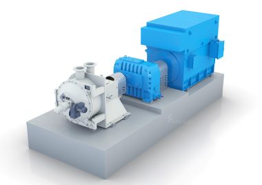
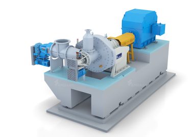
Structure Principle
The machine consists of coupling, spindle and bearing seat, spindle feed mechanism, main engine and electrical control system.
1. Coupling
The machine adopts nylon pin coupling, which is composed of nylon pin shaft, spindle coupling and motor coupling, etc., meeting requirements of axial displacement and torque transmission of spindle. It is easy to install and use and at lower maintenance cost.
2. Spindle and bearing seat
The spindle and three bearings are assembled in the bearing sleeve. The bearing sleeve is provided with an oil filling hole to inject lubricating oil, and an oil level indicator is set at the lower operating side to check the oil level and keep it in a proper position.
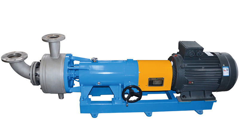
3. Spindle feed mechanism
The spindle feed mechanism is assembled at the rear of the bearing seat (near the side of the spindle coupling), adjust the axial feed rate of the spindle through the hand wheel and turning the handle M1290. After spindle is adjusted to an appropriate position, turn pin spanner and plug pin to lock strictly on the teeth of toothed bearing cap. Before adjusting the feed, the feed limit position of the limit screw M1690 and nut M16 at the end of the bearing chamber must be adjusted first so as to avoid gear ring collision during operation. The axial displacement of the spindle is 0.125mm for each circle of handwheel.
4. Main engine
In this part, fixed outer gear ring, fixed inner gear ring and moving tooth ring make up the deflaking section. The stock is fed in the direction of the spindle axis line and discharged from the pulp outlet above the radial direction. Through the spindle feed mechanism to make it move axially (the maximum movement is less than 7mm) so as to adjust the clearance between the fixed gear ring and the moving gear ring. When starting the machine, the clearance should be more than 1mm, and it should not be less than 0.50mm during normal operation. A drain hole is set at the lower part of the casing to remove the residual stock and dirt during shutdown.
Technical Data
| Project | Parameter |
| Inlet diameter: mm | 125 |
| Outlet diameter: mm | 125 |
| Capacity: t/d | 15-60 |
| Inlet consistency: % | 2—5 |
| Inlet pressure: Mpa | 0.1-0.2 |
| Rotational speed of main engine: r/min | 1480 |
| Power: KW | 37 |