Advantages
- Smaller motor power, lower energy consumption but bigger capacity.
- Centripetal structure, low pulsation, good evenness on web.
- Diffusing outlet design, smooth accept flow, companion flange without spacer, inner surface polishing treatment, seamless connection of pipeline, no fiber hanging.
- Modular design for main motor and drive, stable and reliable structure, easy and fast installation and maintenance.
- Equipped with auto oiling device and mechanical sealing water monitoring and alarming device, detection sensor port reserved to transfer bearing temperature rise and vibration, high automatic level.
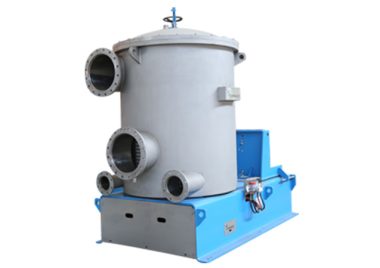
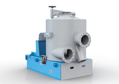
Working Principle
Inflow pressure screen works under pressure in a completely close state to continuously screen. When in operation, pulp slurry tangentially enters the space between screen basket and machine shell from inlet pipe at upper part of the machine body. Under force of pressure difference between inside and outside the basket, accepted pulp passes the screen holes or slots and flows into basket, then discharged through accept pipe at bottom part of machine while debris or rejects slurry failing to pass will drop to bottom and then be discharged through reject pipe. The rotating foils outside the basket produce mild pressure to improve the flow of pulp slurry and negative pressure produced from the tail end causes backflush to holes or slots to prevent fibers or contaminants from binding over the surface, thus to ensure continuous work of screen.
Technical Data
| Model | NLS20 | NLS21 | NLS225 | NLS22 | NLS23 | NLS24 | NLS255 | NLS25 | NLS26 | NLS27 | NLS28 | NLS29 |
| Nominal Area (㎡) | 0.46 | 0.75 | 1.00 | 1.32 | 1.90 | 2.54 | 2.77 | 3.36 | 4.37 | 5.37 | 6.40 | 7.66 |
| InletConsistency (%) | 0.15-1.0 | |||||||||||
| Capacity-Hole (T/D) | 20-40 | 30-60 | 60-100 | 70-130 | 110-160 | 140-260 | 200-300 | 250-400 | 260-520 | 350-600 | 420-700 | 500-900 |
| Capacity-Slot (T/D) | 15-25 | 25-45 | 50-75 | 55-80 | 80-120 | 100-160 | 120-250 | 150-300 | 180-320 | 220-400 | 260-480 | 350-600 |
| Inlet Pressure (MPa) | 0.1-0.4 | 0.1-0.6 | ||||||||||
| Motor Power (KW) | 15 | 18.5 | 22 | 22 | 30 | 37 | 45 | 45 | 55 | 75 | 90 | 110 |
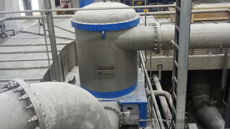
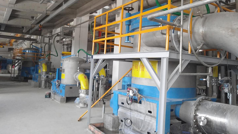
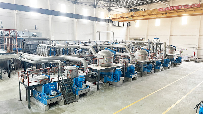
Case
The inflow screen is widely used in the flow system of Tissue paper and packaging paper