
Hydrocyclones can be designed as counterflow or unidirectional flow according to the flow directions of the reject and accept relative to the inlet. In counterflow cyclones, the inlet and accept connections are at one side and the reject outlet is at opposite side. In unidirectional flow cyclones, the accepts and rejects connections are opposite the inlet end.
As Figure 1 shows, both heavy weight (HW) and light weight (LW) cleaners can be counterflow or unidirectional flow. Counterflow HW cleaners have the accepts connection on top and the rejects connection at the bottom of the cone. Counterflow LW cleaners are primarily arranged in the opposite way.
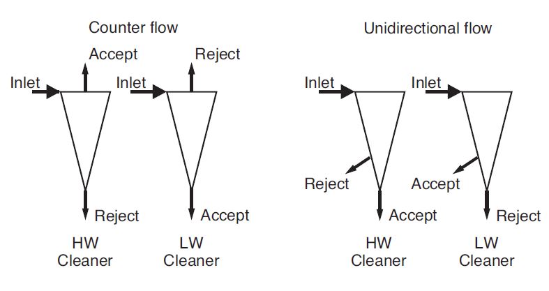
Figure 1. Principles of counterflow and unidirectional flow hydrocyclones for HW and LW cleaning.
Unidirectional flow HW and LW cleaners have both outlets at the bottom of the cyclone cone. The only difference between the units is that HW cleaner reject is removed from the suspension near the wall. In LW cleaners, this is where the accept leaves. This exploits the centrifugal force principle that HW collects on the outside and LW collects on the inside. The HW particles follow a spiral path near the wall to the conical end of the hydrocyclone for removal through the reject opening with a small proportion of the incoming suspension (about 3-15 % by volume or 3-30 % by mass). In counterflow HW cleaners, the accept is taken out as the main flow at the head side of the cyclone.
The LW particles tend to migrate to the centre of the cleaner. In counterflow LW cleaners, light debris is removed with a portion of the total flow (about 3-15 % by volume or 1-15 % by mass) through the reject opening at the head side of the cleaner. Most suspension leaves the cyclone through the accept opening at the conical end. The rejects are removed continuously or intermittently at ambient pressure (continuous only) or under pressure (both techniques). Reverse flushing of fibres occurs only with continuous reject removal.
Cleaners can be operated in any position since the centrifugal force in the apparatus is much higher that than gravity. So installations with vertical or horizontal or even other arrangements of the cleaners can be found.
Installation of hydrocyclones in cleaner batteries
Hydrocyclones cannot be upscaled or downscaled. The separation effect depends strongly on the geometry of the apparatus. A typical production of a single LC cleaner is some hundreds of l/min. In order to achieve the production of a mill a number of cleaners corresponding to this production is needed. For the arrangement of such high number of apparatuses cleaner batteries are designed which allow the connection of cleaners with minimal structural outlay. In Figure 2 three different basic arrangements of such cleaner batteries are shown. To most of such arrangements it is general that the individual cleaners are connected to common inlet, accept and reject pipes or chambers.
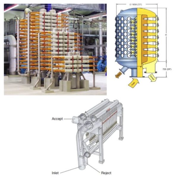
Figure 2. Different cleaner battery arrangements (left top ©Andritz AG, right top ©Noss AB and bottom © J.M. Voith GmbH & Co. KG).
Rejects from the first-stage LC cleaners are processed in as many as four stages depending on system size and the debris content of the incoming suspension. The usual arrangement is cascade. Rejects from the first cleaner stage at production level flow to the second stage at recovery level whose accepts return to the first stage inlet. Rejects from the second stage go to the third cleaner stage whose accepts return to the second stage inlet. The rejects are fed forward to the next higher stage if any until reaching the final cleaner stage. Typical feed consistencies range from 0.8-2 %.
The stock consistency of heavy particle cleaner reject is higher than the inlet consistency. The thickening factor for continuous operation depends on the reject flow ratio, stock type, and type of cleaner. A higher separation efficiency usually corresponds to a higher thickening factor. For cleaners with low volumetric reject rate such as an open, non-pressurised reject outlet, the thickening factor is about 3 – 7. For pressurized cleaners with higher volumetric reject rates, the thickening factor is about 1.5 – 3. This is not solely due to fibre consistency increases since high thickening factors are also the result of an increased amount of fillers and heavy particles contained in the reject.
For efficient handling in the downstream cleaner stages, the rejects require dilution. To reduce flow rates and cleaner size, the stock consistency of the dilution water should be as low as possible. Since flow decreases as it goes through the subsequent stages, the number of cleaners in each stage can be smaller. In heavy particle cleaner systems for example, each stage has only about 25-45 % of the previous stage capacity. The number of cleaners necessary also depends on the thickening factor, reject flow ratio, and dilution water stock consistency.
Cleanliness efficiencies of cleaners depend heavily on throughput. For large changes in output, some cleaners of the first stage should be switched in or out of the system accordingly. The active cleaners can then operate in the optimum range.
Dealing with abrasion in hydrocyclones
Hydrocyclone housings are subject to extremely abrasive heavy particles (metal, glass, sand, fillers, and coating pigments) contained as contaminants in the pulp slurry and to very high flow velocities such as in LC cleaners. Abrasion is especially serious where these particles impact the inner walls with high kinetic energy, travel across the wall surfaces at high velocity, or both. Often the particles remain in almost stationary orbit at a given height in the cyclone. The inlet zone and hydrocyclone cone therefore have a high risk of abrasion.
Abrasion is countered in two different ways. First, the endangered surfaces are protected with ceramic coatings or made entirely of ceramic. Other coating materials such as rubber or hard chromium plating have some use. Second, the design of the hydraulic contours of the hydrocyclone ensure optimum particle flow paths.
Case
-
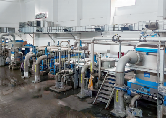 Yunda’s Complete Stock Preparation System for Jinlong’s 6600 mm Packaging Paper Project Enters Commissioning Stage
-
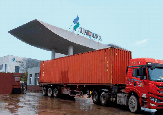 Key Pulping Equipment Supplied by Yunda for Uzbekistan International Paper’s Tissue Paper Upgrade Project Successfully Shipped
-
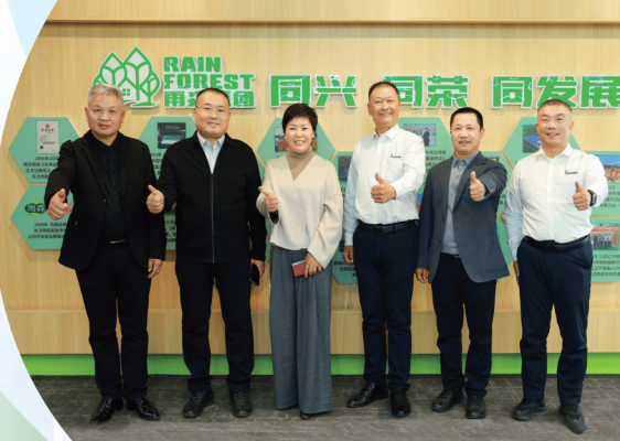 Yunda Secures Orders for Premium Tissue Paper Projects at Two Yusen Group Production Bases
-
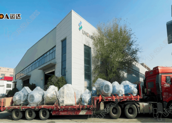 Yunda Successfully Ships the Complete Stock Preparation System for Hengan Group’s Tissue Paper Project
-
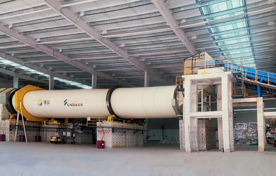 Yunda’s Complete Stock Preparation Systems for Guangxi Xiongfu Paper’s 300,000 t/a Grayboard Paper Project Successfully Start Up
-
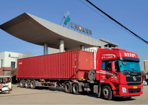 Yunda Successfully Ships Complete Stock Preparation and Broke Handling Systems for BAOBAB Paper’s Tissue Paper Project in Zimbabwe
-
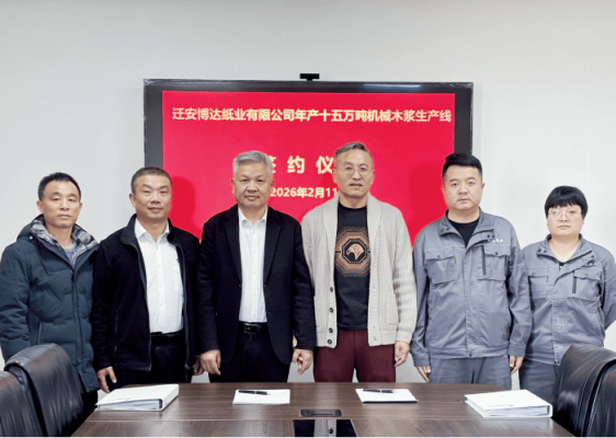 Yunda Wins the Full-Line Pulping Equipment Order for Qian’an Boda’s 150,000-Ton Bleached Chemi-Thermomechanical Pulp (BCTMP) Project
-
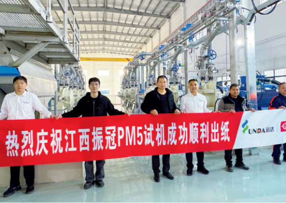 A Great Start! Yunda’s Complete Stock Preparation System Supports Successful First Paper Production on Jiangxi Zhenguan PM5
-
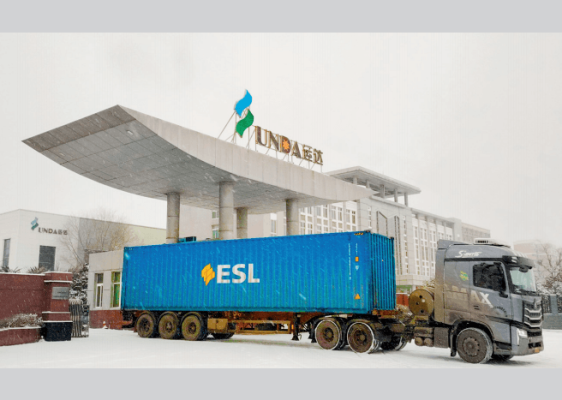 Yunda Ships Key Stock Preparation Equipment for Egypt’s Sama Pack Packaging Paper Project
-
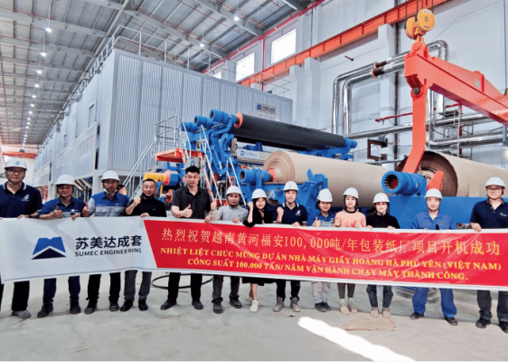 Yunda Successfully Commissions Complete Stock Preparation and Approach Flow Systems for Vietnam Huanghe’s 100,000-Ton Packaging Paper Project