Installation
Overview
This section outlines the steps for transporting, storing, and installing the equipment.
These steps are essential for transport and installation companies to understand and carry out responsibly.
Safety Regulations
Strict adherence to the safety instructions in this section is mandatory. Failure to follow these guidelines could result in personal injury or even loss of life. Do not ignore safety protocols.
General Safety Regulations
Comply with all safety and accident prevention rules.
Analyze potential risks caused by compressed gases and steam; implement appropriate safety measures.
Do not exceed the lifting weight limit of hoisting devices and ropes. Ensure suspended components do not fall from heights.
Never stand beneath suspended equipment as it poses a life-threatening danger.
Prevent tipping during transportation and equipment installation.
Assign Qualified Personnel
Transportation, disassembly, and installation must be carried out by personnel familiar with the tasks.
Personnel responsible for lifting and transporting the equipment must hold the required national certifications.
Installation should only be performed by trained and skilled personnel.
Personal Protection
Always wear safety gear and personal protective equipment while working.
Welding Equipment
Use welding equipment suitable for the task and adhere to welding operation guidelines.
Transportation
Secure the equipment during transport to prevent it from falling from heights or off the transport vehicle, which could cause accidents or fatalities.
Do not remove any fixed or limiting devices from the equipment during transfer or lifting operations.
When lifting the entire equipment with multiple types of lifting lugs, ensure the lugs meet the weight requirements.
Do not stand or walk under suspended equipment.
Refer to the transportation documents for the equipment's dimensions and weight.
Inspect the shipment and packaging for integrity.
If damage or shortages are found during transportation, do not accept the goods and
notify both the shipping agent and the after-sales department of YunDa Paper Machinery Co.,Ltd.
Storage
If immediate installation is not possible, adhere to the following storage instructions:
1.Notify the after-sales service department of YunDa Paper Machinery Co., Ltd.
2.Provide necessary protection for the stored equipment.
3.Store the equipment in an environment that avoids large temperature fluctuations and ensures cleanliness and dryness.
4.Do not remove the packaging before installation.
Installation
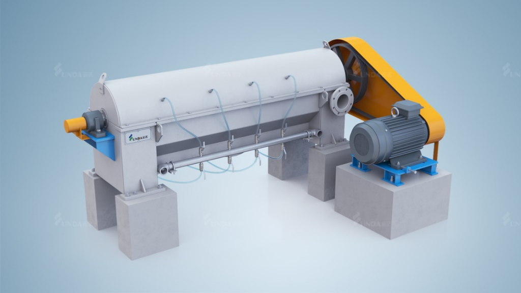
(1).Installation Requirements: Ensure the horizontal alignment; the pulley parallel deviation
must not exceed 1 mm.
Bearing lubrication: The support bearings for the drive shaft use grease lubrication.
For ease of oiling, lubrication pipes are extended from the bearing housing to the outer
wall of the equipment.
(2).Lubrication Grease Specification: Lithium-based grease.
(3).Lubrication Interval: Weekly: Add 5-10 grams of grease.
Startup
Overview
This chapter outlines the preparations and steps necessary for the initial startup of the machine.
Safety Regulations
All safety instructions in this section must be strictly followed!
General Safety Regulations:
Adhere to all applicable accident prevention rules.
Implement proper safety measures.
Identify and prevent potential risks associated with gas and steam formation.
Assign Qualified Personnel: Startup operations should only be performed by trained and skilled personnel.
Attention: During the startup process, the safety protection system is always active,
posing a risk of immediate activation of safety devices. Potential hazards must be highlighted during safety training.
Personal Protection: Personal safety equipment must be worn at all times during work.
Startup Conditions
Pre-Startup Inspection
Before starting the equipment, perform the following checks:
1.Ensure all protective covers and guards are installed and secured.
2.Verify there are no loose, worn, damaged, or missing parts.
3.Confirm all personnel have cleared the equipment.
Rotor/Screen Frame Clearance
Initially, the clearance between the rotor and the screen frame should be 2.0–2.5 mm. This clearance is ensured by machining the rotor blades to a specific height. Over time, the clearance may increase, at which point the blades should be replaced. This clearance is ensured by machining the rotor blades to a specific height. Over time, the clearance may increase, at which point the blades should be replaced.
Note: When checking the clearance between the rotor and the screen, the cover must be removed.
Startup Procedure
1.Open the spray water and dilution water valves.
2.Start the motor.
3.Gradually open the feedstock valve.
4.Check for motor overload.
5.Verify that the flow rates of accept pulp and reject pulp are appropriate.
Since the rotor speed is fixed, maintain a stable feedstock consistency and flow rate for optimal performance.
Feedstock Consistency Range: Typically below 2.5%.
Maximum Capacity: 30 air-dry tons per day.
Shutdown Procedure
1.Stop feeding stock.
2.Continue running the machine until the system is free of pulp.
3.Turn off the motor.
4.Close the spray water and dilution water valves.
5.Ensure the equipment is in a zero-mechanical state.
Common Operational Issues and Consequences If the current rises or vibrations increase, it is likely due to high reject consistency from upstream equipment. Adjust promptly. Failure to address this issue can cause internal bolts to loosen, leading to equipment damage.
Maintenance
Routine Maintenance
Conduct a major inspection at least every three months or 1,000 hours of operation. Identifying and resolving minor faults early can extend the equipment’s service life. Regular Inspections Detect and resolve minor faults to extend fault-free operating time, reduce unplanned downtime, and lower costs. Before performing maintenance or inspection, follow the shutdown procedure, lock out all power sources, and ensure the equipment is in a zero-mechanical state.
Fault Diagnosis
Fault Diagnosis Guide:
| issue | possible cause |
| low load | Low speed: V-belt slippage or wear. |
| high load or excessive noise | Screen frame blockage high screening consistency hardened or blocked rejects rotor blade contact with screen frame damaged mechanical components (e.g., bearings, loose blades). |
| abnormal vibration | rotor imbalance or blockage feed fluctuations loose motor bolts excessive bearing clearance |
| high fiber loss | excessive feed rate high feed consistency blocked dilution water pipes. |
| v-belt slippage | rotor blockage loose belt, or contamination by oil or water. |
| excess rejects in good pulp | low flow rate damaged screen frame. |
Disassembly and Assembly
Disassembling the Protective Cover
1)Open one of the feed ports and check the slurry flow through the sight glass.
2)If the flow is insufficient or absent, remove the protective cover.
3)If the pulp drips, recheck the feed valve, dilution water valve, and flushing water valve.
4)Loosen and remove all bolts and gaskets, including those on the shaft seal cover.
5)Lift the protective cover and place it next to the equipment.
6)Avoid placing the protective cover directly on the floor; support it with clean wooden blocks.
7)Before inspecting or repairing internal components, flush and clean them to remove pulp and debris. Inspect for wear or damage on the inner surface of the cover.
8)Check rotor assembly, screen frame wear, clearance, blade tightness or damage, bearing condition, and screen frame wear or damage.
9)Based on the inspection results, repair or replace components if necessary. Full rotor disassembly may not be required.
10)Reinstall the protective cover in its original position. The installation steps are the reverse of removal.
Disassembling the Rotor
1)Remove the V-belt and shaft protective covers. Loosen the motor bolts to slacken the belt.
2)Remove the belt.
3)Detach the seal covers on both ends.
4)Remove the upper covers of the thrust bearing housings on both ends.
5)Note: The pulley and bearings do not need to be removed at this stage.
6)Secure a nylon rope to the rotor and lift it out of the equipment.
Note: Use an auxiliary lifting beam. Rotor removal is generally unnecessary unless damaged.
Once the rotor is safely removed and supported, proceed with the following:
The rotor blades are radially mounted on the cylindrical shaft in matching rows. Each
blade is secured with two bolts, and the bolts should be spot-welded to prevent loosening.
Grind off and remove old bolts.
Note: Do not reuse old bolts; new bolts are supplied with the blades.
Replace blades row by row, tightening and spot-welding bolts before proceeding to the next row.
Not all blades may need replacement. Before reinstalling the rotor, perform these checks:
1)Inspect pulleys and belts.
2)Clean the bearing housings if necessary.
3)Clean the screen plate if needed.
4)Ensure spray nozzles are unobstructed.
5)If the screen plate is worn, rotate and reinstall it in a new direction.
6)Clear the discharge outlet.
7)Reinstall the rotor by reversing the disassembly steps.
Disconnect the spray water pipe on the accepts side of the screen plate through the operation-side handhole.
Remove the bolts securing the screen plate and the corner brackets on both sides.
Attach four lifting lugs to the screw holes on the screen plate’s edges to act as jackscrews.
Extract the screen plate.
Note: Lifting lugs must be provided by the customer.
Follow the reverse order of removal steps.
Installing the Mechanical Lip Seal
Clean the shaft.
Install the lip seal onto the fixing plate.
Secure the seal housing onto the bearing using bolts.
Case
-
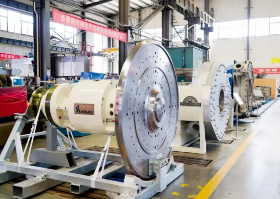 Yunda Supplies High-Consistency Refiner S2070 Drive Assembly to JSC, Belarus
-
 Russia Khargi Packaging Paper Project
-
 350,000 tpy Linerboard Project in Arkhangelsk, Russia
-
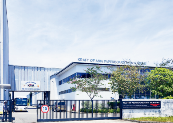 KOA Vietnam 6600/1100 Packaging Paper Upgrade Project
-
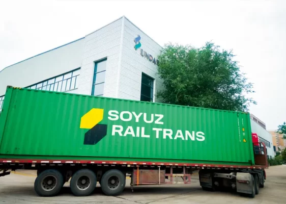
 Smooth Shipment of Complete Thermo Mechanical Pulping Equipment for Thailand Precise Molding Project
-
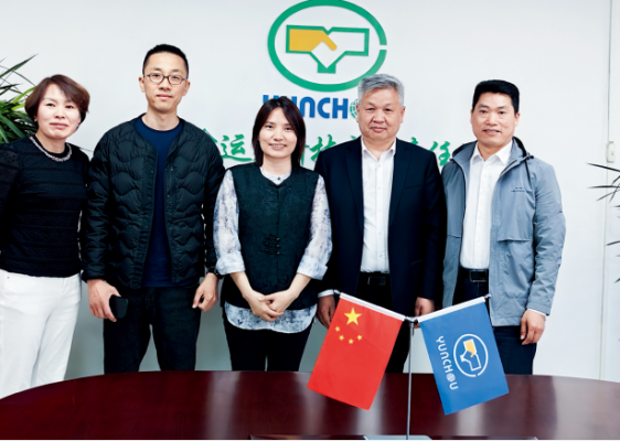
 Successful Delivery of the Refiner Repair Project Between Yunda and Guangzhou Paper Group
-
 100,000 Tons Per Year Cultural Paper Project in Ethiopia
-
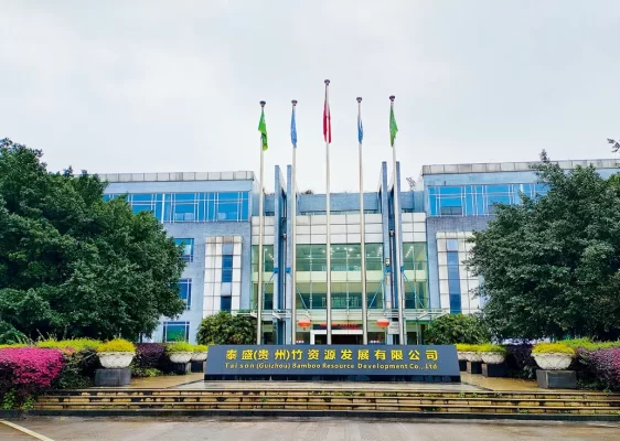 Taison (Guizhou) 160,000 tons tissue paper project
-
 Taison Tissue Paper Project
-
 Guangxi Xiongfu Paper Project