One basic characterisation of the rheology of a fluid is the description of the correlation between the forces acting on a fluid,
f.i. in form of a pressure gradient, and the shear forces or the shear stress occurring in the fluid. If we consider a simple pipe flow as sketched in Figure 1, the driving force of the flow is the pressure gradient Δp and the resulting forces in the fluid can be characterised by the gradient of the local velocity u(y). The resulting wall shear stress then can be expressed by the pressure gradient and some information about the pipe geometry by the following Equation (1):
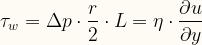
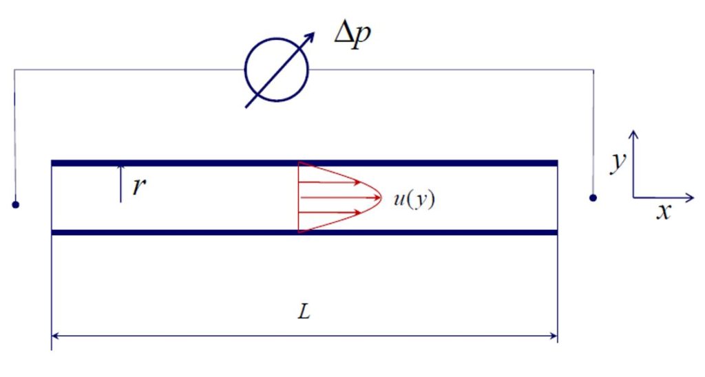
The correlation factor in this equation between wall shear stress and velocity gradient is the so called viscosity η. If the viscosity is independent from the velocity the fluid is called Newtonian. Water is a well know Newtonian fluid. Fibre suspension is a Non-Newtonian fluid with a quite complex non-linear viscosity and in addition to that in many applications of fibre suspension wall effects between the fibres and the wall cannot be neglected. Furthermore, a fibre suspension is a multiphase and multicomponent fluid This makes fibre suspension very unique and one has to be very careful in transferring experiences and knowledge gained from Newtonian fluids like water to fibre suspensions. Figure 2 compares the rheological fingerprint of water with that of fibre suspensions in the form of a shear stress versus velocity gradient diagram. More practical diagrams of pressure drop versus average flow velocity have the same shape.
The basic effects of fibre suspensions are explained in the following:
- Flow limit
Pulp suspensions behave like ketchup: If one starts pumping with very low pressure – or in the ketchup example one just opens and turns the bottle – he will not see any effect. The suspension needs some “energy of activation” before it starts flowing – like the Ketchup needs some agitating. The effect is caused by the fibres forming a network sticking to the wall. The lower the consistency and the shorter the fibres, the less strong this effect is. Below consistencies of about roughly 1 % to 2 % it does not play a significant role. - Nonlaminar flow
In fibre suspensions laminar flow is not possible at all. Except for very low consistencies fluid dynamic knowledge for laminar flows cannot be applied for fibre suspensions. In the region of low energy input or low shear stress the fibres form a network or plug and the suspension flows in so called plug flow. - Fibre free wall layer
When the fibre suspension starts to flow, the fibres close to the wall turn and orient themselves in the main flow direction (in average). This results in an almost fibre free wall layer which has the average thickness of about half of the mean fibre length. This water layer at the wall forms a lubrication film and reduces the energy needed for pumping. The suspension continues to flow in the form of a plug flow. - Deflocculation
Increasing shear forces in the suspension introduced by increasing pressure gradient deflocculates the pulp. This effect starts at the wall with the wall effect and first breaks the fibre network into smaller flocks and later the flocks into single fibres. - Fluidised suspension and turbulent flow
The deflocculating effect continues with increasing pressure gradient until all fibres are individualised and in average oriented in the main flow direction. At this point the curve for fibre suspension crosses the curve for water. The corresponding shear stress of this point is called the [[critical shear stress]] . The critical shear stress is the minimum shear stress required for deflocculating the pulp. This is an important information since for separation processes like flotation or screening the pulp suspension has to be deflocculated in order to individualise fibres and debris particles. An interesting effect is that pumping fluidised fibre suspension in turbulent flow needs less energy than pumping water. This effect can be seen in industrial applications when f. i. a pressure screen is operated with water only and then fed with fibre suspension. The power consumption of the motor will drop significantly. The explanation for this phenomenon is that the fibres in the suspension dampen the turbulence and therefore less energy is dissipated in turbulent flow of fibre suspension than of pure water.
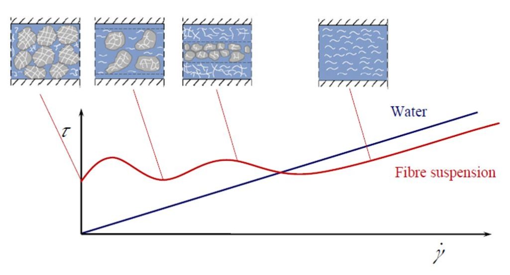
The particles in the suspension must be separated to allow fibres or other useful particles to be recovered in the separation process. Therefore, the shear stress is a very important parameter from which the minimum amount of energy required for reaching fluidisation of the suspension and individualisation of particles can be calculated. is a function of the pulp consistency with an exponential correlation in the form
Typical values for the constants k1 and k2 in this equation are given in Table 1 It has to be emphasised that the absolute values calculated this equation depend on the device the measurements are made with. But for relative comparisons of different pulps this approach is very useful.
Table 1. Constants for calculating the fluidisation shear stress Ƭc with given as a percentage 1
| Pulp type | k1 | k2 |
|---|---|---|
| Softwood bleached kraft | 3.12 | 2.79 |
| Groundwood | 1.08 | 3.36 |
| TMP | 2.63 | 3.56 |
The critical shear stress is significantly affected by pH and filler content. Alkaline pH causes fibre swelling and makes the fibres more lubricated. This results in lower values for Ƭc. Filler particles also reduce the tendency of fibres to form flocks and by this decrease Ƭc, too. In Figure 3 the critical shear stress is plotted qualitatively versus the consistency. Such an exponential curve can be approximated by two lines.
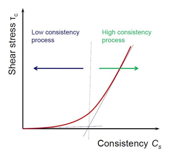
The transition point is the point where the two lines cross. Let’s call processes with consistencies smaller than this edge consistency low consistency (LC) processes and processes with higher consistencies high consistency (HC) processes. In LC processes fluidisation of the pulp with increasing consistency needs only little more energy. In HC processes an only slight increase in consistency results in a dramatic higher amount of energy required for fluidisation. From this point of view the optimum operation point for separation processes would be in the LC range slightly before the point where the curve starts to grow exponentially. There the compromise between minimum dilution of the pulp and minimum energy required for fluidisation is very good.
In industrial practice processes are operated to far left from this point in many cases from an energy efficiency point of view. One reason is the risk to run into the HC region when raw material composition or process conditions vary. In such cases the efficiencies of separation processes like cleaning, flotation or screening drop drastically. Sensors for measuring the rheological properties of the suspension could help operating the processes close to the optimum consistency and save energy by processing less water. But such sensors are not available today.
Source https://forestbiofacts.com/
Case
-
 Yunda Supplies High-Consistency Refiner S2070 Drive Assembly to JSC, Belarus
-
 Russia Khargi Packaging Paper Project
-
 350,000 tpy Linerboard Project in Arkhangelsk, Russia
-
 KOA Vietnam 6600/1100 Packaging Paper Upgrade Project
-
 Smooth Shipment of Complete Thermo Mechanical Pulping Equipment for Thailand Precise Molding Project
-
 Successful Delivery of the Refiner Repair Project Between Yunda and Guangzhou Paper Group
-
 Taison Tissue Paper Project
-
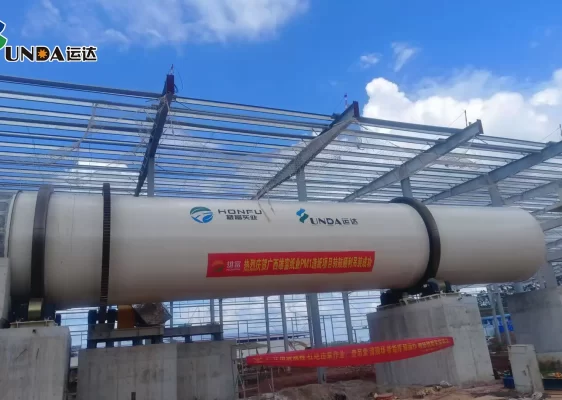 Guangxi Xiongfu Paper Project
-
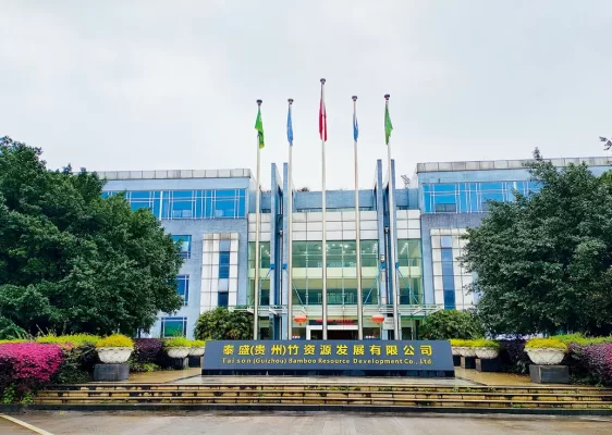 Taison (Guizhou) 160,000 tons tissue paper project
-
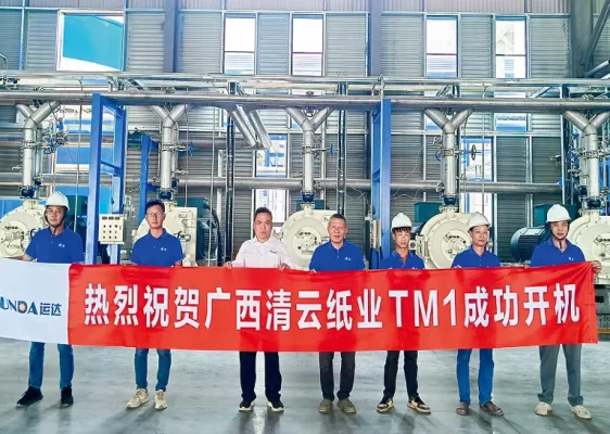 Guangxi Qingyun Tissue Paper project