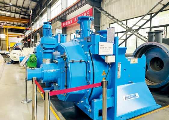
Equipment Overview
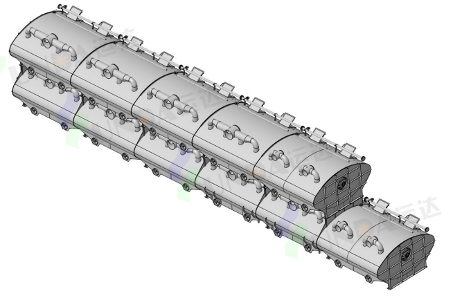
The flotation deinking cell is the core equipment in the waste paper deinking pulping process. It is mainly used to remove ink particles, stickies, fillers, and other impurities from waste paper pulp through the flotation process. Its core function is to utilize air bubbles to adsorb ink particles, thereby purifying the pulp and improving the brightness and quality of recycled pulp.
Equipment Parameters
| Item | Specification |
|---|---|
| Model | TMCA300 |
| Quantity | 1 Set |
| Stages | 2 |
| Raw Material | Old Book Paper |
| Inlet Flow Rate | 26,400 L/min |
| Inlet Consistency | 0.8–1% |
| Number of 1st Stage Cells | 5 |
| Number of 2nd Stage Cells | 2 |
| Number of Injectors per 1st Stage Cell | 5 |
| Total Number of 1st Stage Injectors | 25 |
| Number of Injectors per 2nd Stage Cell | 2 |
| Total Number of 2nd Stage Injectors | 4 |
| Equipment Overall Dimensions (L × W × H) | Approx. 25,300 × 3,900 × 4,770 mm |
| Foam Overflow Rate at 1st Stage Weir Plate | 150–250 L/min per meter of flotation cell length |
| Foam Overflow Rate at 2nd Stage Weir Plate | 80–150 L/min per meter of flotation cell length |
| Spray/Cleaning Device Pressure | 0.3 ± 0.2 MPa |
| Washing Facility | — |
| 1st & 2nd Stage Washing Interval | 2–6 h |
| 1st Stage Washing Time | 10–30 s |
| 2nd Stage Washing Time | 30–60 s |
Structure of Flotation Deinking Cell
| Item | Component |
|---|---|
| 1 | Pulp Inlet Distribution Pipe |
| 2 | Injector |
| 3 | Overflow Weir Plate |
| 4 | Overflow Weir Plate Cleaning Device |
| 5 | Foam Breaking Spray Device |
| 6 | Adjustable Ink Weir Plate |
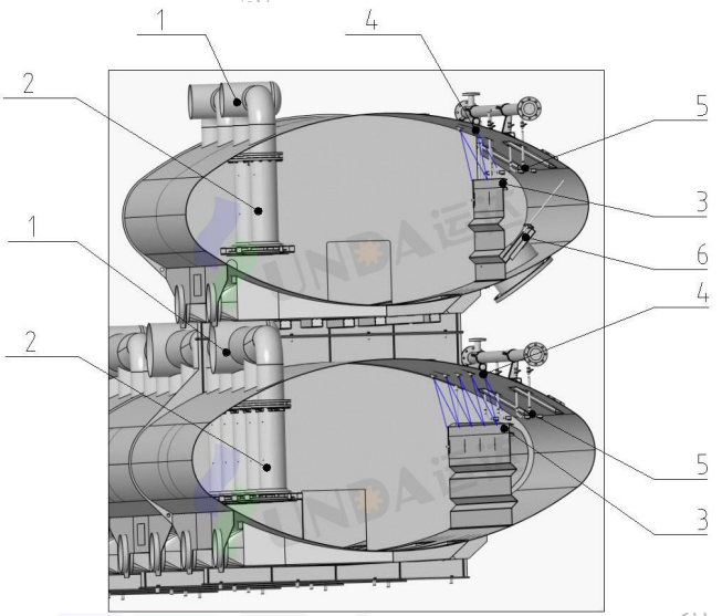
Structure Diagram of Flotation Deinking Cell (Lower Section: 1st Stage, Upper Section: 2nd Stage)
Deinking Principle
- The first-stage flotation system consists of several flotation cells connected in series. The pulp containing ink and particles enters the flotation cell through the injector at the bottom of the first chamber. After purification in the first chamber, the pulp is pumped into the injector of the second chamber, and the process continues sequentially until the last chamber. The accepted stock from the final chamber of the first stage enters the next process. Foam containing ink from each chamber flows into the foam collection header through the adjusted overflow weir plate.
- Openings are provided at the bottom of the partitions between adjacent chambers, with the upper edge of each opening positioned below the pulp and foam overflow surface. In this way, the flotation deinking cell is composed of several interconnected flotation chambers. These openings help balance the liquid levels among the chambers.
- Two types of level transmitters are used to regulate the overflow volume and control the accepted stock valve. One transmitter is installed in the flotation zone of the flotation chamber (flotation cell level transmitter), while the other is installed in the foam collection tank (foam collection tank level transmitter).
- The flotation cell level transmitter is used to control the pulp level in each flotation chamber. Its basic setpoint is determined during commissioning according to the specific process conditions of each mill. The foam collection tank level transmitter is used to control the foam overflow volume, which is related to the opening of the ink weir plate and the transmitter setpoint. If the actual liquid level of the retained “ink” in the foam collection tank deviates from the preset value, the ink collection tank control system sends a signal to the flotation cell control system to adjust the pulp level setpoint in the cell, thereby generating a corresponding adjustment parameter. This control method ensures stable liquid levels in the flotation cells.
- The foam from the first and second stages is separately collected in their respective foam collection tanks. Spray water is used in the collection tanks to break the foam and convert it into ink slurry. The ink from the first stage flows through the adjusted adjustable ink weir plate into the ink collection header, then enters the first-stage defoamer before flowing into the first-stage ink collection tank. The ink separated from the first-stage flotation cell is pumped from the first-stage ink collection tank to the second-stage flotation cell.
- Most of the fibers contained in the first-stage ink slurry are recovered in the second-stage flotation process and pumped back to the first-stage flotation cell.
- Similar to the first-stage flotation cell, the liquid level of the second-stage flotation cell is also regulated by controlling the overflow foam volume. The second-stage ink slurry is discharged into the ink tank or trench.
Case
-
 Taison Tissue Paper Project
-
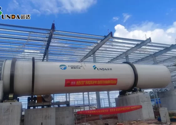
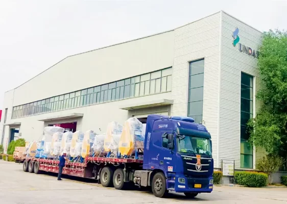
 Smooth Shipment of Complete Thermo Mechanical Pulping Equipment for Thailand Precise Molding Project
-
 Guangxi Xiongfu Paper Project
-
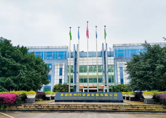 Taison (Guizhou) 160,000 tons tissue paper project
-
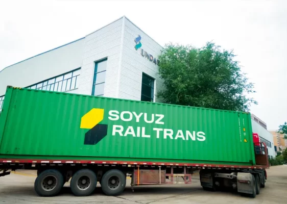 Russia Khargi Packaging Paper Project
-
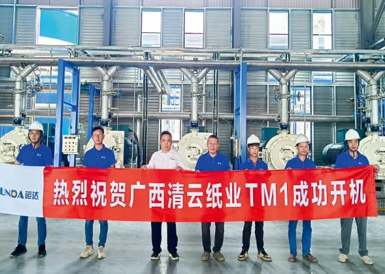 Guangxi Qingyun Tissue Paper project
-
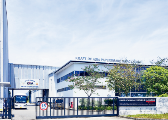 KOA Vietnam 6600/1100 Packaging Paper Upgrade Project
-
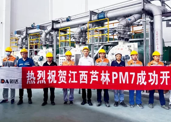 Jiangxi Lulin’s 200,000-ton packaging paper project
-
 Successful Delivery of the Refiner Repair Project Between Yunda and Guangzhou Paper Group
-
 100,000 Tons Per Year Cultural Paper Project in Ethiopia