
LC pulpers
LC pulpers process recovered paper in loose form or bales that require opening but not necessarily dewiring. LC pulpers are most commonly used in recovered paper processing for manufacturing packaging paper and board. Figure 4 shows the basic Iayout of an LC pulper for stock consistencies up to about 6 %. Pulpers of this type now have a volume as high as 160 m3. The pulping forces are generated by the impeller that rotates at a peripheral speed of 12-20 m/s.
The rotor shaft can be vertical, horizontal or oblique. ln most cases, LC pulpers operate in the continuous mode with constant removal of the almost completely slushed stock through the screen plate. lmpeller blades keep this free. The extraction screen plate hole diameter can vary from 6 to 20 mm, depending on the system design and recovered paper grade. Smaller holes result in smaller flakes in the accepts but require Ionger pulping times. With larger holes, the pulping time is shorter but flakes in the accepts are larger in size and amount. The hole diameter can only be optimised by considering the downstream screening system that must not be overloaded by excessive flake size or quantities. Easily pulpable stocks are often reduced to a flake content of 15-20 %. With more difficult stocks, these figures approach 20-40 %. To prevent excessive concentrations of trash in continuously operating pulpers, it needs to be removed continuously. Figure 5 shows a typical pulper discharge system for this purpose. Part of the suspension is extracted from the pulper and pumped via a junk separator to a disk screen that also acts as a deflaker. The accepts are pumped toward while the rejects are sorted in a drum screen. Accepts from this drum screen are recirculated to the pulper, while the rejects are discarded.

Bale wires, strings, pieces of plastic, foils and textiles are often removed from the pulper by a ragging device consisting of a winch, followed by a tail cutter. This system operates on the principle that this type of junk is formed into a tail under certain conditions. To start ragging, a length of barbed wire is placed into the tub. Due to the intensive rotary flow in the neighbourhood of the impeller, spinning materials become entangled. The tail accumulates and becomes increasingly langer. lt is continuously pulled from the pulper by a winch at a speed that must not exceed the tail growth rate.
LC pulpers are particularly suitable for repulping wet-strength grades in batch operation. For more intensive repulping on the bottom of the pulper vat, stationary bars are fitted around the rotor periphery. The recovered paper can be further treated by heating to 75 °C or more and adding chemicals, although this is more cost-effective with HC pulpers.
Drum pulpers
Drum pulpers operate in a most gentle manner compared to HC, MC and LC pulpers. This makes them very suitable for pulping recovered paper while avoiding the disintegration of contaminants which have to be separated later in the process. The basic Iayout of a drum pulper is shown in Figure 6.

The most common applications are for old newspapers and magazines. Due to the comparatively gentle forces in drum pulpers they are used for low-wet-strength papers in particular. Advantages of drum pulpers are their continuous operation and robustness against large contaminants.
Drum pulpers rotate at circumferential speeds of 100-120 m/min, measuring 2.5 – 4 m in diameter and up to 30 m in length. They obviously require considerable space. They are driven on the periphery by friction using truck tyres or by a gear ring and pinion transmission. They gently incline toward the rejects end. The drum has two zones, one for repulping, the other for screening. These either form a rigid unit or are separated and rotate in opposite directions. The repulping zone requires about two-thirds of the drum length. The screening zone uses the remaining third. The loose recovered paper or broken down dewired bales are fed into the repulping zone with water and any chemicals required such as for deinking. Inside the repulping zone are carrier claws for the stock. Drums operate at a consistency of about 14-20 % in the repulping area.
As the drum rotates, the stock moves upward, as shown in Figure 7. Depending on the filling Ievel, a flowing or rolling motion occurs that exerts shear forces for efficient slushing. The stock that falls freely from the top of the drum undergoes the greatest slushing forces. Since these forces are generally lower than in pulpers, the contaminant particle size remains sufficiently large for good screening.

The wet-strength components of recovered paper mixtures cannot be slushed and therefore end up in the rejects. In the screening zone of the drum, the stock consistency is reduced with dilution water to about 3-5 % in the accepts. The hole diameter is about 6-9 mm. The coarse contaminants and flakes usually comprising wet strength materials reach the end of the drum as low-fibre rejects. The accepts are deflaked and coarse-screened.
Figure 8 shows a drum pulper with two separate drums and two different zones for repulping and screening. The advantage of this design is that operating parameters like circumferential speed and retention time can be adjusted independently of each other for both zones.

To utilise the advantages of drum pulpers for paper grades with higher wet strength, a repulping drum equipped with a “displacement core” is available. Such drums are equipped with a-shaped element inside the drum in order to increase the friction and shear forces acting on the fibres in the channel between the rotating drum and the fixed displacement core. In this design, the impact on the falling stock is increased as illustrated in Figure 9 due to the bigger distance the stock is falling down after passing the channel. The increased fall supports the disintegration.

Case
-
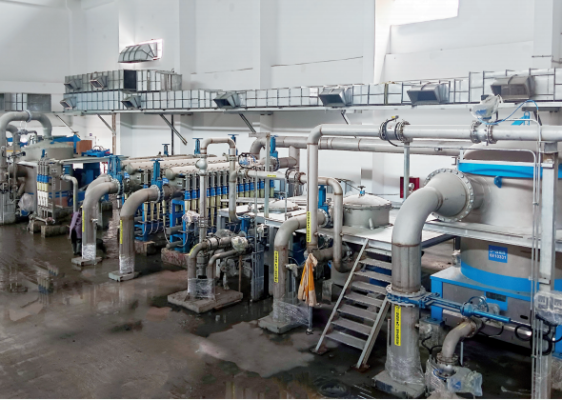 Yunda’s Complete Stock Preparation System for Jinlong’s 6600 mm Packaging Paper Project Enters Commissioning Stage
-
 Yunda Secures Orders for Premium Tissue Paper Projects at Two Yusen Group Production Bases
-
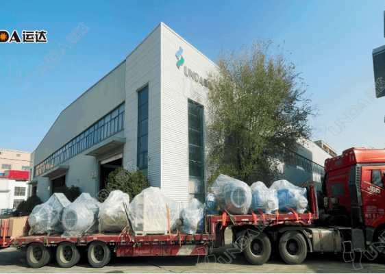 Yunda Successfully Ships the Complete Stock Preparation System for Hengan Group’s Tissue Paper Project
-
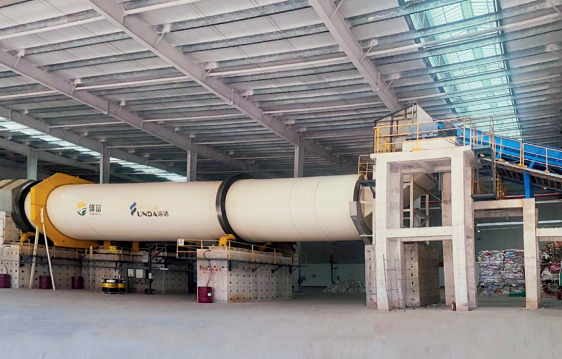 Yunda’s Complete Stock Preparation Systems for Guangxi Xiongfu Paper’s 300,000 t/a Grayboard Paper Project Successfully Start Up
-
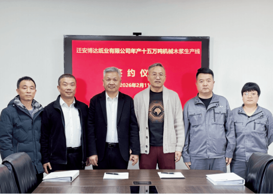 Yunda Wins the Full-Line Pulping Equipment Order for Qian’an Boda’s 150,000-Ton Bleached Chemi-Thermomechanical Pulp (BCTMP) Project
-
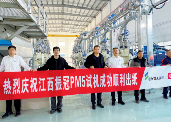 A Great Start! Yunda’s Complete Stock Preparation System Supports Successful First Paper Production on Jiangxi Zhenguan PM5
-
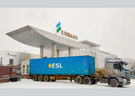 Yunda Ships Key Stock Preparation Equipment for Egypt’s Sama Pack Packaging Paper Project
-
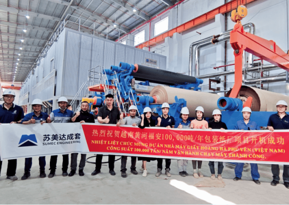 Yunda Successfully Commissions Complete Stock Preparation and Approach Flow Systems for Vietnam Huanghe’s 100,000-Ton Packaging Paper Project
-
 Yunda Successfully Starts Up Complete Stock Preparation and Approach Flow Systems for Jiangmen Renke Oasis 80,000 TPA Tissue Paper Project
-
 Successful Start-Up of Taisheng Group’s Tissue Paper Project in Guizhou